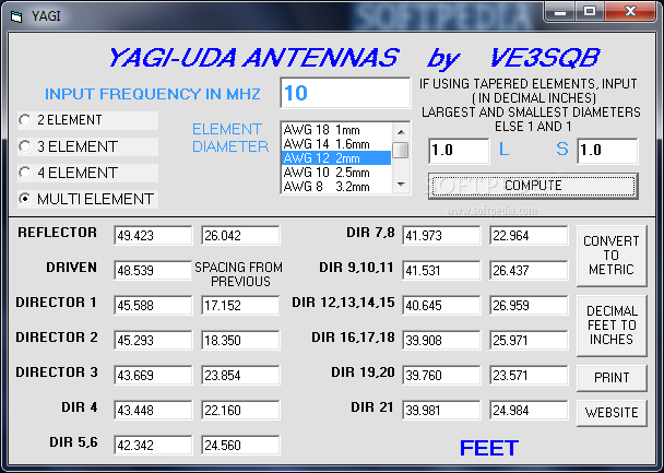
Yagi Antenna Design Software Free Download
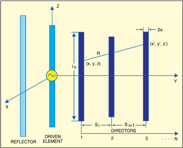
The file MEI-10.ZIP contains educational software to evaluate antenna arrays of up to 8 elements. Two types of arrays may be studied: 2D planar arrays (Yagi-Uda, Circular, etc., up to 6 elements) and colinear arrays (up to 8 elements.).
TheW8IO / WB0DGF Antenna Site
(30 March 2015)
NEC Software for Yagi Design
- It could be that the antenna is designed in free space, and you had to mount the elements to a boom to make it. The boom adds negative reactance to the elements. This not a problem on hf, a minor problem on 2 meters, very noticeable on 440 mhz and can destroy a 1.2 ghz design.
- About YagiMax 311 The resource is currently listed in dxzone.com in 2 categories. The main category is Antenna analysis software that is about software,antenna analysis software, for ham radio operators and hams. This link is listed in our web site directory since Sunday Jan 3 2010, and till today 'YagiMax 311' has been followed for a total of 4105 times.
| Software / Version / Author | Type of Yagi Design | Input/Open/Import File Formats | Save/Export File Formats | Price |
| 4NEC2 version 5.8.14 Arie Voors | - | .nec .ez (EZNEC) .ant (AO) | .nec .txt | Free |
| EZNEC version 5 Roy Lewallen W7EL | - | .ez (EZNEC) .en | .ez | EZNEC v. 5 ($89) EZNEC+ v.5 ($139) EZNEC Pro/2 v.5 ($500) |
| AutoEZ Demo 2.0.10 Dan Maguire AC6LA | - | .weq (AutoEZ) .ez (EZNEC) .nec .ant (AO) .inp .maa (MMANA-GAL) | .weq (AutoEZ) .ez (EZNEC) | Demo - Free full version - $79 |
| YagiCAD 6.2.0 Paul McMahon VK3DIP | includes sample Yagi files | .yc6 (YagiCAD) .yag (YagiCAD) | .yc6 (YagiCAD) .nec .nec (4NEC2) .txt | Free |
| YW - Yagi for Windows 2.0 Dean Straw N6BV | - | .yw (Yagi for Windows) .yag (YO) | .yw (Yagi for Windows) | included in ARRL Antenna Handbook |
| Yagi Calculator 2.6.10 John Drew VK5DJ | DL6WU long boom Yagi creation | no file import | .yag (YO) .maa (MMANA-GAL) | Free |
| CocoaNEC 2.0 Kok Chen W7AY | - | .nec | ? | Free (Mac OS-X version of NEC) |
| MMANA-GAL | - | ? | ? | ? |
| NEC2GO | - | .nec | .nec | $39.95 |
Note: K6STI's AO and YO software no longer available. His older versions will not work in Windows 7 and 8.
NEC/MININEC-basedSoftware Vendors:

EMScientific:'New'MININEC Free'Expert MININEC Classic' software - badlink?
EZNEC/EZNEC+andEZNECPro (W7EL)
NEC-WinPlus, NEC-Win Pro, GNEC 'NittanyScientific' - now out ofbusiness
OrionMicrosytems:NEC4WIN MININEC Software'NEC4WIN95' - do not order fromKAGI?
SuperNEC 'SuperNEC' NEC2/UTDcombo
4NEC2 FreeNEC-2 software with excellent GUI - new web site 3-1-13
NEC2++ from Tim Molteno (discussionforum)
AutoEZ,TLDetails&MoxGen by Dan Maguire AC6LA
MMANAFreesoftware based on MININEC from DL2KQ-EU1TT
CocoaNECFreeNEC software for the Mac OS-X Tiger operating system by W7AY
OtherMOM-based Software Providers:
WIPL-DMethod of Moments software
ANSYSDesigner 2D+Code for Patch Antenna Design (FreeStudentVersion - no longer available)
MentorGraphics Software (was IE3D) 2D+Code for Patch Antenna Design
AntennaDesign Freeware fromMeyers Engineering
MOMICMethod of Moments Interactive Code - notavailable?
NEC-BSCNEC Basic Scattering Code, ESP -Electromagnetic Surface Patch Code andothers(Ohio State)
YagiCAD6.2.0freeYagi-specific Windows software by VK3DIP
YagiModeler Applet online applet tosimulate Yagis by W9CF
FEA-basedSoftware Vendors:
ANSYSHFSS3D Antenna Structure Simulator
AntennaStructural Analysis Software:
NEC/MININECOrganizations and Resources:

The(Unofficial) NEC Archives(WB6TPU) FreeSoftware!
NEC-2informationUsers Manual for NEC and other information
L.B.Cebik'sAntennaSite (W4RNL) Hundreds ofAntenna Articles!
Other RFand Antenna Software
(links updated 18 Feb 2013)
Learn HowAntennas Work!
LinearDipole - set length to 0.5(half-wavelength dipole) and notice that theimpedance is near 73 ohms. Radiation pattern shown is typicalfigure-8pattern. When a half-wave dipole is close to ground, the impedance isloweredto near 50 ohms. Thus a perfect match to 50 ohm cable.
-set lengthto 1.27 wavelength. This is called an Extended Double Zeppantenna and produces the maximum gain possible from a simple center-feddipole. Notice that the radiation resistance (impedance) is about 90ohms. This antenna can be matched to 50 ohms by using a seriesinductor.Half of this antenna is 5/8 wave and is a common length for 2m mobileantennas.The 5/8 wave antenna is typically fed against a ground plane (car roof)andis usually matched with a tapped inductor.
-set lengthof dipole to multiples of 1/4 wave on each side (e.g. 0.5, 1.5,2.5, etc.). Notice how these lengths produce an radiationresistance(impedance) close to 100 ohms. The patterns of these are madeup ofmany lobes (cloverleaf pattern).
How doantennas produce gain?
dB,dBi, dBd What is dBi? What is dBd? What is an isotropicradiator? Part 1 in a series from LB Cebik W4RNL
Wheredoesthe gain come from? Part 3 in a series from LB Cebik W4RNL
updated 17 Jan 2006
LincolnAmateur Radio Club Antenna Class
Links to Software and other information
4NEC2 FreeNEC-2 software with excellent GUI
AgilentAppCAD Transmission Lines and more
MIMPMotorola Impedance Matching Program (select zip file and download)
NECTutorial - Learn how to createNEC input files
NECUser Guides (HTML &PDF)
SmithChartresources (articles, softwareand charts)
AntennaModelingSoftwarefrom Dan Maguire AC6LA (MultiNEC, Moxon generator, TLDetails, etc.)
KB0YKI'sRadio Zone (onlineJ-Pole Designer, online Yagi Designer, the 'Copper Cactus' doubleJ-Pole)
PCAAD2.1 Software to helpdesign wire, horn and patch antennas - by Dave Pozar
updated ?
LPCAD - Log Periodic CAD
Now availablefor Windows 7 OS!
LPCAD version 3.4 is nowavailable! LPCAD 3.4runs fine underWindows 2000, XP, Vista and Windows 7. Please emailme at rgcox2 (at) gmail.com for details.
updated 18 Feb2013
Yagi Antenna Design Calculator
NEC ModelLibrary
The following files and links point to NEC/AO/YO models of various Hamantennasthat I have simulated and/or tested over the past 30 years as anantennadesigner. The NEC files may be used with any of the NEC-2 or NEC-4programssuch as 4NEC2, GNEC or cocoaNEC, however some of them with taperedelementsmay only be simulated accurately by NEC-4 or other MININEC-basedsoftware.These models will indicate in the CM lines if they need to use NEC-4 or4NEC2.These models have varying degrees of accuracy. Some may be very closetoactual performance. Others may only be an estimate. They are for you,asthe experimenter, to use and improve. This list will grow asI checkeach file before uploading, so check back often. Have fun!
Links:
W3LPLYagi Designs for 40,20, 15 and 10m
VHF NECModels:
28DX a 13.4 dBi low backlobe Yagi for 144.2 on a 12' 6' boom
215DXa 16.35 dBi low backlobe high-performance Yagi for 144.2 MHz (metricdimensions)
216CP (AO file) a very experimental RHCP 2m beam with 12.3 dBicgain and single point feed
216CP(NEC file) - updated 2-4-06 - improved axial ratio & VSWR
23DFa 3 element Yagi for 2m Foxhunting (7.7 dBi & 40 dB F/B)
25FBa 5 element 4' 4' boom Yagi for 2m Foxhunting (9.4 dBi& 34 dB F/B)
26FB a 6 element 6' 6' boom Yagi for 2m Foxhunting (10.4dBi & 34 dB F/B)
27FB a 7 element 8' 6' boom Yagi for 2m Foxhunting (11dBi & 36 dB F/B)
6m_3el_yagi an8.1 dBi low backlobe Yagi for 50.1 on a 6' boom
6m_4el_yagi a9.8 dBi Yagi for 50.1 on a 12' 6' boom (use in 4NEC2)
6m_moxona 6.2 dBi 'Moxon rectangle' for 50.1 MHz
- LP50-108-16 (NEC file) a Log-Periodic Dipole Array for 50-108 MHz, 8 dBi, 30 dB F/R on 6m, 12' boom
The VHF antennas shown above include the 'raw' element lengths. Thatis, the element lengths are those used with a wood or plastic(dielectric)boom or supported above or below a metal boom with an large insulator.Toconvert these raw lengths into actual lengths used when passed throughthecenter of metal booms, you need to add a correction factor, based onwhetherthe element is insulated and passes through the center of a metal boom,oris shorted directly to the metal boom with a clamp.

If theelement is insulated when it passes through the metal boom, thecorrectionfactor is approximately 1/4 the diameter of the boom. Forexample,for a 36' (raw length) insulated element passed through the center of a1'metal boom, the correction factor is 0.25', so the actual length shouldbe36.25' when built.
(updated 16 July 2013)
Commentsare welcome!

contactRoger: email to WB0DGF @ ARRL.NET
or
rgcox2(at) gmail.com
Yagi Antenna Design
Roger Cox - Spring Lake, MI